Company Details

Xi'an Gavin Electronic Technology Co., Ltd
Company Details
Xi'an Gavin Electronic Technology Co., Ltd


 January 07, 2022
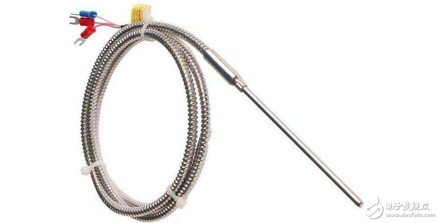
The pt100 Temperature Sensor is a meter that converts temperature variables into a standardized output signal that can be transmitted. Mainly used for measurement and control of industrial process temperature parameters. A transmitter with a sensor usually consists of two parts: a sensor and a signal converter. The sensor is mainly a thermocouple or a thermal resistor; the signal converter is mainly composed of a measuring unit, a signal processing and a conversion unit (since the industrial thermal resistance and the thermocouple indexing table are standardized, the signal converter is also called as a stand-alone product). Transmitter), some transmitters have added display units, and some have fieldbus functionality.
Temperature is one of the most physical parameters in nature and dealing with human beings. Whether in production or experimental places, temperature collection or control is very frequent and important. Moreover, networked remote acquisition of temperature and alarm is modern technology. An inevitable trend in development. Since the temperature has a close relationship from the physical quantity itself or the actual people's life, the Temperature sensor will be generated accordingly.
Due to the relationship between the temperature and the resistance of the PT100 thermal resistance, it is convenient to use this characteristic to invent and produce the PT100 thermal resistance temperature sensor. It is a smart sensor that integrates temperature and humidity collection. The temperature can be collected from -200 °C to +850 °C, and the humidity collection range is from 0% to 100%.
Working principle of pt100 temperature sensor working circuitPT100 is a positive temperature coefficient thermistor. What is the positive temperature coefficient? It must be combined with the negative temperature coefficient. As the temperature increases, the resistance of the resistor becomes larger, which is the thermistor of the positive temperature coefficient. On the contrary, if the resistance of the resistor becomes smaller as the temperature rises, it is the thermistor with a negative temperature coefficient.
The PT100 is widely used not only because it can measure a wide temperature range (a few tens of degrees below zero to a few hundred degrees above zero), but also because its linearity is very good. "Linearity", the straightforward point is that for every degree of temperature change, the magnitude of the resistance increase is basically the same. This greatly simplifies our program.
However, PT100 also has its shortcomings, that is, for every degree of temperature rise, the resistance change is too small, only 0.39 ohms. This requires high-precision, low-noise conversion on the hardware.
There are many circuits circulating on the Internet, and many circuits cannot be used as products. Here is a high-precision circuit for everyone, which is a bit high cost, but good quality.
For Temperature Measurement circuits, there are actually many places worth studying, and small circuits have great wisdom. For example, can you see at a glance that this circuit can't measure the temperature under zero? Can you calculate the temperature range from which this circuit can measure? Can you modify this circuit so that it can measure the temperature range you need? What happens if you swap the two lines of inverting (-IN) and in-phase (+IN)?
Look, you think the circuit is simple, then the above questions can be answered?
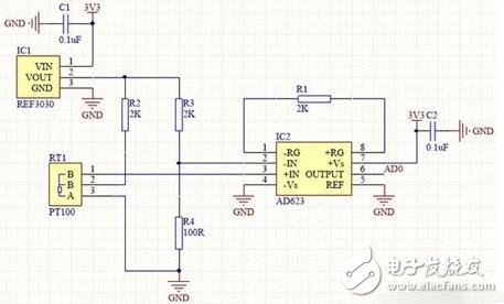
Circuit explanation:
The simpler the circuit, the better the stability. All four resistors in this circuit require 0.1% accuracy. The circuit uses only one bridge and one differential amplifier. R2 R3 R4 and PT100 form a bridge circuit, and REF3030 provides a standard 3.00V voltage for the bridge circuit. The AD623 uses a 2K amplified feedback resistor to accurately amplify the bridge's voltage differential by a factor of 51. (Why is 51 times, see the AD623 datasheet for details)
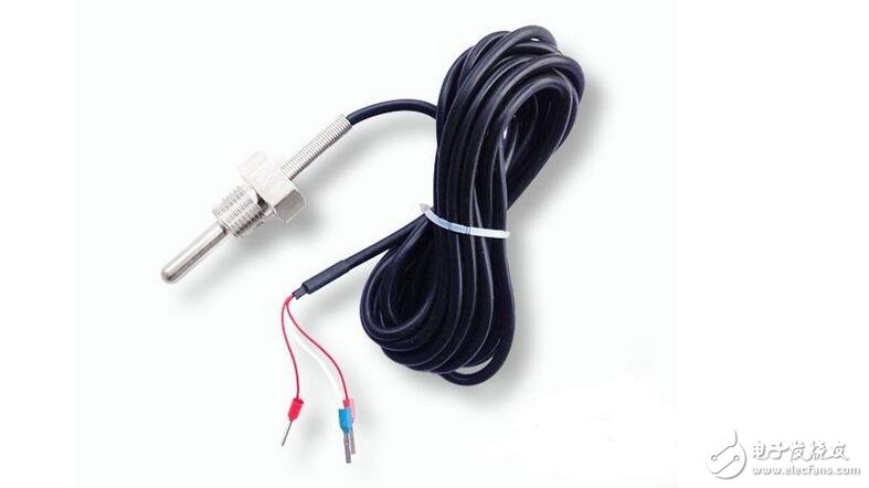
PT100 connection method:
Careful little friends will study the connection of PT100. The PT100 generally has two and three wire sensors. Because the line itself must have resistance, and as mentioned above, for every change, PT100 only changes 0.39 ohms. If the line of PT100 is very long, the resistance will be larger, the line will be different, the resistance will be different, it will definitely be big. Affect the measured results. So, you can understand now, the two-wire PT100 is only suitable for short-distance applications. For long-distance applications, a three-wire system is required. Let us see how the three-wire system eliminates the effects of resistance on the wires. Forget it, let's talk about it in the next article. It is necessary to draw a few pictures to make it clear. It is not too late, too lazy to draw.
Temperature range:
Assuming that it is now 0 degrees, then the resistance of PT100 is 100 ohms. In the circuit, the voltage difference of the bridge is 0V, so the final is also 0V, that is, when 0V is measured, it is 0 degrees. Suppose now that the next zero degree, the resistance of PT100 is less than 100 ohms, the voltage of the same phase will be smaller than the voltage of the reverse phase, and the obtained voltage will always be 0V, so this circuit will not measure below 0 degrees.
The maximum output of AD623 is 3.3V, 3300/51=64.7mV. That is to say, the voltage difference of the bridge can only be 64.7mV, and the larger the voltage difference, the output of AD623 is also 3.3V. The voltage of the inverting arm is fixed at (3000/2100)*100=142.86mV, so the voltage of the same phase arm can only be 142.86+64.7=207.56mV, and the resistance of PT100 is equal to 207.56/((3000-207.56)/ 2000) = 148.66 ohms.
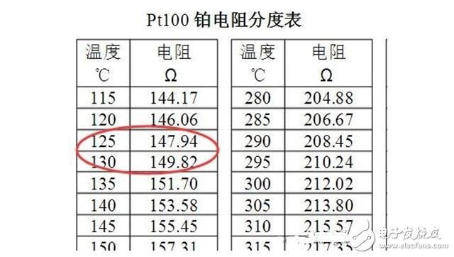
Then look up the table, you can see that the maximum temperature measurement point is almost 127 degrees. Therefore, the temperature range of this circuit is 0~127 degrees.
Selection and verification method of verification point of pt100 thermocouple temperature sensorPt100 verification point selection and basic method
1. For each verification point of Pt100, select 0°C and 100°C, and check the compliance of the actual resistance temperature coefficient a;
2. When △a does not meet the requirements, the temperature of the upper limit (or lower limit) of the effective temperature range of the corresponding tolerance class in Table 1 shall be checked;
3, Pt100 and second-class standard platinum resistance thermometer resistance measurement, should use four-wire measurement method;
4. When the Pt100 is verified, the thermal resistance current should be no more than 1 mA. It is better to use a digital multimeter that meets the measurement accuracy requirements. The platinum resistance method is alternately repeated no less than 4 times (including current commutation), and the average value is taken separately. As a measurement result.
Verification of R0 (resistance at 0 °C)
1. In the freezing point tank (or the constant temperature tank with 0 °C, the deviation does not exceed ±0.2 °C), measure the resistance value of Pt100 and the temperature measured by the second-class standard platinum resistance thermometer, and compare and calculate the deviation value of 0 °C. △t0;
2. The thermal resistance that can be removed from the protection tube should be placed in a glass test tube with an inner diameter slightly larger than the diameter of the temperature sensing element. After the nozzle is tightly plugged with cotton wool or cork, insert the ice water into the ice point tank. The insertion depth should not be Less than 30mm;
3. The non-removable Pt100 thermal resistance of the protection tube can be directly inserted into the medium, and the measurement data can be read when the measurement data is stable;
4. If a 0°C thermostat is used, the Pt100 thermal resistance should have sufficient insertion depth to minimize heat loss;
5. Verify the Pt100 thermal resistance above AA level. In order to reduce the test uncertainty, it should be measured in the water triple point bottle.
Verification of R100 (resistance value at 100 °C) and Rt (resistance at temperature t°C)
1. Measure the resistance value of Pt100 thermal resistance R100 in a constant temperature bath at 100 ° C, and compare it with the temperature measured by a second-class standard platinum resistance thermometer, and calculate the deviation value Δt100 of 100 ° C;
2, the Rt test of the detachable Pt100 thermal resistance is the same as the R0 test, the temperature sensing element is placed in the glass test tube (the test temperature should be placed in the quartz test tube above 400 °C);
3. Insert the thermostatic bath and ensure sufficient insertion depth. After the heat balance, continue to increase the insertion depth of l0mm. After the heat balance is reached again, the resistance value should not exceed 5% of the allowable error.
4. When the temperature t is higher than 500 ° C, the thermal resistance should be cooled to 0 ° C with the rate of less than 1 ° C / min, and then taken out from the temperature control tank;
5. The temperature of the test point of the constant temperature bath should not exceed ± 2 ° C, and the change within 10 min should not exceed ± 0.02 ° C.
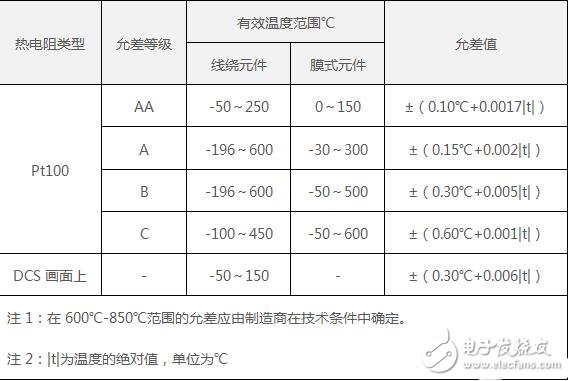
Industrial Pt100 Thermal Resistance Allowance Error Table
Qualified judgment of R0 and R100 resistance values
1. In the effective temperature range, the maximum deviation between the temperature t and the true temperature of the resistance value of the thermal resistance through the index table shall not exceed the tolerance value given in the above table.
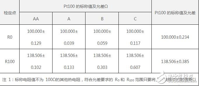
2. The nominal values of Pt100 (platinum resistance with resistance value of 100 at 0 °C) and Cu100 (copper resistance with resistance value of 100 at 0 °C) and the ranges of R0 and R100 that meet the tolerance requirements are shown in the table below.
The above is the The working circuit and principle of pt100 temperature sensor and the verification point selection of pt100 temperature sensor we have listed for you. You can submit the following form to obtain more industry information we provide for you.
You can visit our website or contact us, and we will provide the latest consultation and solutions
Send Inquiry
Most Popular
lastest New
Related Products
Send Inquiry