Company Details

Xi'an Gavin Electronic Technology Co., Ltd
Company Details
Xi'an Gavin Electronic Technology Co., Ltd


 July 22, 2022
1. Introduction to Temperature And Humidity Sensor
1.1 Temperature and humidity related concepts
Since temperature and humidity are closely related to temperature and humidity, both from the physical quantity itself and in the actual life of the people, the temperature and humidity integrated sensor will be generated accordingly. The temperature and humidity sensor refers to a device or device that can convert the amount of temperature and humidity into an electrical signal that is easily measured and processed. Temperature and humidity sensors on the market generally measure the amount of temperature and the amount of relative humidity.
Temperature: The physical quantity that measures the hot and cold of an object is one of the seven basic physical quantities in the International System of Units. In production and scientific research, many physical phenomena and chemical processes are carried out at a certain temperature, and people's lives are closely related to him.
Humidity: There is a close relationship with life long before the humidity, but it is more difficult to express it by quantity.
The most common physical quantity of humidity used in daily life is the relative humidity of the air. Expressed in %RH. Relative humidity has a close relationship with temperature in the derivation of physical quantities. A certain volume of closed gas, the higher the temperature, the lower the relative humidity, and the lower the temperature, the higher the relative humidity. It involves complex thermal engineering knowledge.
Some definitions of humidity:
Absolute humidity: refers to the amount of water vapor actually contained in the air per unit volume, usually in grams. Temperature has a direct effect on absolute humidity. Under normal circumstances, the higher the temperature, the more water vapor is emitted, and the greater the absolute humidity; on the contrary, the absolute humidity is small.
Saturated humidity: The maximum amount of water vapor that can be contained in the air per unit volume at a certain temperature. If this limit is exceeded, excess water vapor will condense and become water droplets, and the air humidity at this time becomes called saturated humidity. The saturated humidity of the air is not fixed and it changes with temperature. The higher the temperature, the more water vapor can be contained in a unit volume of air, and the greater the saturation humidity.
Dew point: refers to air containing a certain amount of water vapor (absolute humidity). When the temperature drops to a certain level, the water vapor will reach saturation.
(saturated humidity) and begins to liquefy into water. This phenomenon is called condensation. The temperature at which water vapor begins to liquefy into water is called "dew point temperature" and is referred to as "dew point". If the temperature continues to drop below the dew point, the supersaturated water vapor in the air will condense into water droplets on the surface of the object. In addition, the wind is closely related to the temperature and humidity in the air, and is also one of the important factors affecting the temperature and humidity changes of the air.
1.2 Measurement method of temperature and humidity
Humidity measurement technology has been around for a long time. With the development of electronic technology, modern measurement technology has also developed rapidly. Humidity measurement is divided into two or thirty in principle. The means of expressing humidity are absolute humidity, relative humidity, dew point, moisture to dry gas ratio (weight or volume), and the like. But humidity measurement has always been one of the most famous problems in the world of metrology. A seemingly simple measure of value, involving a fairly complex physical-chemical theoretical analysis and calculations, may involve neglecting many of the factors that must be noted in humidity measurement, and thus the rational use of the effects. Common methods of measuring humidity include: dynamic method (double pressure method, double temperature method, split method), static method (saturated salt method, sulfuric acid method), dew point method, dry and wet ball method and various electronic sensor methods. The double pressure method and the double temperature method are based on the thermodynamic P, V, and T balance principles, and the equilibrium time is long. The split method is based on the precise mixing of absolute moisture and absolute dry air. Due to the use of modern measurement and control methods, these devices can be made quite sophisticated, but because of the complexity and cost of the equipment, the operation is time-consuming and labor-intensive, mainly used as a standard measurement, the measurement accuracy can reach ± 2% RH - ± 1.5% RH. The saturated salt method in the static method is the most common method in humidity measurement and is simple and easy. However, the saturated salt method requires strict balance between liquid and gas phases, and requires high stability to ambient temperature. It is required to wait for a long time to balance, and the low humidity point requires longer. Especially when the indoor humidity and the humidity inside the bottle are large, it needs to be balanced for 6~8 hours each time. The dew point method is to measure the temperature at which the humid air reaches saturation. It is a direct result of thermodynamics, with high accuracy and wide measurement range. The accuracy of the precision dew point meter for measurement can reach ±0.2 °C or even higher. However, the cold mirror dew point meter using the modern light-electric principle is expensive and often used in conjunction with a standard humidity generator.
The wet and dry ball method, which was invented in the 18th century. It has a long history and is most commonly used. The dry-wet ball method is an indirect method that converts the humidity value using the dry-wet ball equation, which is conditional: the wind speed near the wet ball must be above 2.5 m/s. The normal dry and wet bulb thermometer simplifies this condition, so its accuracy is only 5~7% RH, which is significantly lower than the electronic humidity sensor. Obviously, dry and wet balls are not static methods. Do not simply think that increasing the measurement accuracy of two thermometers is equivalent to improving the measurement accuracy of the hygrometer. Two points are emphasized here: First, since humidity is a function of temperature, temperature changes decisively influence the measurement of humidity. Regardless of the method, accurately measuring and controlling the temperature is the first. It should be noted that even in a well-insulated constant temperature and humidity chamber, there is a certain gradient in the temperature in the working chamber. Therefore, the humidity in this space is also difficult to be completely uniform. Second, due to the large differences in principles and methods, it is difficult to directly calibrate and identify various measurement methods, and most of them can only be compared by indirect methods. Therefore, it is very difficult to calibrate the measurement results of the full wet range (relative humidity 0~100% RH) between the two moisture measuring methods, or to calibrate the measurement results of each point in all temperature ranges. For example, a ventilated dry and wet bulb hygrometer requires a flow of air with a specified wind speed, while a saturated salt method requires a strict seal, which cannot be compared. The best way is to determine the transfer method and verification procedures specified by the state for the humidity measurement instrument verification system (standard).
2 digital temperature and humidity sensor DHT11
2.1 Introduction to DHT11
The DHT11 digital temperature and humidity sensor is a temperature and humidity composite sensor with a calibrated digital signal output. It uses dedicated digital module acquisition technology and temperature and humidity sensing technology to ensure high reliability and excellent long-term stability. The sensor consists of a resistive wet sensor and an NTC Temperature Sensor connected to a high performance 8-bit microcontroller. Therefore, the product has the advantages of excellent quality, ultra-fast response, strong anti-interference ability and high cost performance. Each DHT11 sensor is calibrated in an extremely accurate humidity calibration chamber. The calibration coefficients are stored in the OTP memory as a program, and these calibration coefficients are called internally during the processing of the detection signal. The single-wire serial interface makes system integration easy and fast. Ultra-small size, extremely low power consumption, and signal transmission distances of up to 20 meters make it the best choice for even the most demanding applications. The product is available in a 4-pin single-row lead package. Easy to connect, special package form can be provided according to user needs.

Figure 4.5.2 DHT11 product physical map
2.2DHT11 application field
DHT11 is widely used in the following aspects: HVAC, air conditioning, testing and testing equipment, automotive data loggers, consumer goods automatic control, weather stations, home appliances, humidity regulators, Medical, dehumidifiers
2.3DHT11 product features
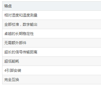
2.4DHT11 dimensions
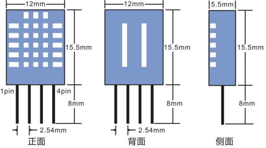
Figure 4.5.3 Dimensional Drawing of DHT11
2.5 Product parameters 2.5.1 Product circuit diagram
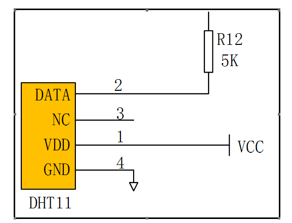
Figure 4.5.4 DHT11 pin diagram
2.5.2 DHT11 pin description
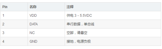
Table 4.5.1 DHT11 Pin Description
2.5 Electrical characteristics VDD = 5V, T = 25 ° C, unless specifically marked
Table 4.5.3 Electrical Characteristics of DHT11

Note: The sampling period interval must not be less than 1 second. 2.6 typical circuit
2.6.1 Typical Application 1 It is recommended to use a 5K pull-up resistor when the length of the cable is shorter than 20 meters, and use a suitable pull-up resistor according to the actual situation when it is greater than 20 meters. The schematic is shown in Figure 4.5.5

Figure 4.5.5 DHT11 Typical Application 1
2.6.2 Typical Application 2 Microprocessor Connection to DHT11 The typical application circuit is shown in Figure 4.5.7. After DATA is pulled up, it is connected to the I/O port of the microprocessor.
1. In the typical application circuit, it is recommended to use a 5.1K pull-up resistor for a cable length shorter than 20 meters. When the cable length is greater than 20 meters, reduce the resistance of the pull-up resistor according to the actual situation. (2) When using 3.5V voltage supply, the length of the connecting line should not exceed 20cm. Otherwise, the line voltage drop will cause insufficient power supply to the sensor, causing measurement deviation. (3) The temperature and humidity value read each time is the result of the last measurement. To obtain real-time data, it needs to be read twice in succession. However, it is not recommended to read the sensor multiple times in succession. Each time the sensor interval is greater than 5 seconds, Get accurate data.
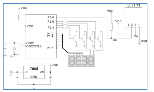
Figure 4.5.6 DHT11 Typical Application 2
2.7 Serial Communication Description (Single-Wire Bidirectional) 2.7.1 Single Bus Description The DHT11 device uses simplified single-bus communication. A single bus has only one data line, and data exchange and control in the system are all completed by a single bus. The device (master or slave) is connected to the data line via an open-drain or tri-state port to allow the device to release the bus when it is not transmitting data, and to allow other devices to use the bus; a single bus typically requires an external 5.1kΩ The pull-up resistor is such that when the bus is idle, its state is high. Since they are master-slave poles, the slave can only respond when the master calls the slave. Therefore, the master access device must strictly follow the single bus sequence. If there is a sequence chaos, the device will not respond to the host.
2.7.2 Single bus transfer and data bit definition
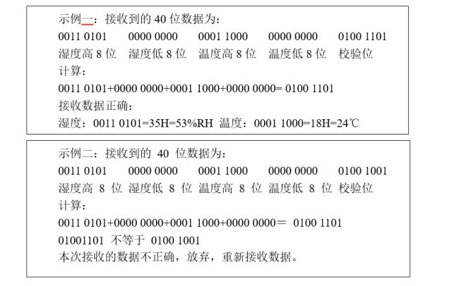
DATA is used for communication and synchronization between the microprocessor and DHT11. It uses a single bus data format to transfer 40 bits of data at a time, high first out.
Data format: 8bit humidity integer data + 8bit humidity decimal data +8bit temperature integer data + 8bit temperature decimal data +8bit check digit.
2.7.3 Check Digit Data Definition
2.8 data timing diagram
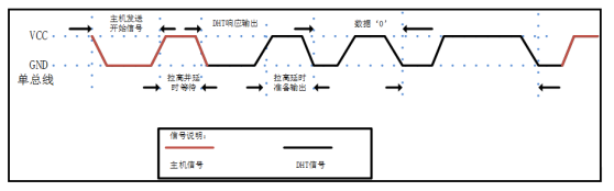
Figure 4.5.7 Data Timing Diagram
The bus idle state is high, the host pulls the bus low and waits for the DHT11 response. The host must pull the bus low for more than 18 milliseconds to ensure that the DHT11 can detect the start signal. After receiving the start signal of the host, the DHT11 waits for the start signal of the host to end, and then sends an 80us low-level response signal. After the host sends a start signal, the delay waits for 20-40us, then reads the response signal of the DHT11, and the host sends a start signal. After that, you can switch to the input mode, or the output can be high, and the bus is pulled high by the pull-up resistor.
The bus is low, indicating that the DHT11 sends a response signal. After the DHT11 sends the response signal, the bus is pulled high by 80us, ready to send data. Each bit data starts with a 50us low time slot, and the high level determines the data. The bit is 0 or 1. The format is shown below. If the read response signal is high, the DHT11 does not respond. Please check if the line is connected properly. When the last bit of data is transferred, DHT11 pulls the bus 50us, then The bus is pulled high by the pull-up resistor to the idle state.

Figure 4.5.8 Host sends start signal and slave response signal
The digital 0 signal representation method is shown in Figure 3.

Figure 4.5.9 Digital 0 signal representation
The digital 1 signal representation method is shown in Figure 4.5.10.
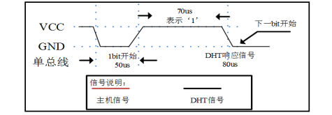
Figure 4.5.10 Digital 0 signal representation
2.9 Application Information
2.9.1 Operating and Storage Conditions Exceeding the recommended operating range may result in temporary drift signals of up to 3% RH. After returning to the normal working bar, the sensor will slowly return to the calibration state. Prolonged use under abnormal operating conditions will accelerate the aging process of the product.
2.9.2 Exposure to Chemicals The sensing layer of a resistive humidity sensor is subject to chemical vapors, and the diffusion of chemicals in the sensing layer may cause drift in measured values and reduced sensitivity. In a pure environment, pollutants are slowly released. The recovery process described below will speed up the process. High concentrations of chemical contamination can cause complete damage to the sensing layer of the sensor.
2.9.3 Recovery treatment Sensors placed under extreme operating conditions or in chemical vapors can be restored to the state they were in during calibration by the following procedure. It was kept at 50-60 ° C and humidity of < 10% RH for 2 hours (drying); then maintained at 20-30 ° C and >70% RH humidity for more than 5 hours.
2.9.4 Temperature effects The relative humidity of a gas depends to a large extent on temperature. Therefore, when measuring humidity, the humidity sensor should be operated at the same temperature as much as possible. If a printed circuit board is shared with the heat-releasing electronic components, the DHT 11 should be kept away from the electronic components as much as possible and installed under the heat source while maintaining good ventilation of the casing. To reduce heat transfer, the copper plating of the DHT11 and other parts of the printed circuit board should be as small as possible with a gap between the two.
2.9.5 light
Prolonged exposure to sunlight or intense ultraviolet radiation can degrade performance. 2.9.6 Wiring Precautions
DATA signal wire quality will affect the communication distance and communication quality. It is recommended to use high quality shielded wire.
3. DHT11 process for obtaining temperature and humidity
The flow chart of the temperature and humidity acquisition program is shown in Figure 4.5.12.
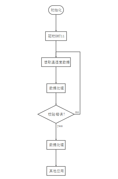
Figure 4.5.12 Temperature Acquisition and Processing Process (Flowchart is drawn by MD syntax)
The flow of the subroutine for temperature acquisition is shown in Figure 4.5.13.

Figure 4.5.12 Temperature Acquisition Subfunction (flowchart drawn by MD syntax)
Fourth, the experimental content
1. Laboratory equipment connection
The physical diagram of the vibration sensor used in this experiment is shown in Figure 4.5.14.
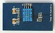
Figure 4.5.14 DHT11 module physical map
Install the temperature and humidity sensing module on the development board, and then connect one end of the JLINK emulator to the computer with a USB interface. The 20Pin JTAG pin on one end is connected to J2 of the NXP LPC2378 node board, and the NXP LPC2378 node is powered on. As shown in Figure 4.5.15.
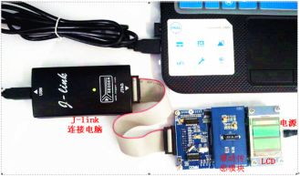
Figure 4.5.15 Experimental circuit connection diagram
2. Temperature and humidity measurement experiment
The temperature and humidity in the laboratory are measured by the DHT11 module and displayed on the screen through the LCD to simulate the temperature and humidity functions on the perpetual calendar. The specific code is not posted here.
The above is the Introduction to temperature and humidity sensor, digital temperature and humidity sensor DHT11 introduction we have listed for you. You can submit the following form to obtain more industry information we provide for you.
You can visit our website or contact us, and we will provide the latest consultation and solutions
Send Inquiry
Most Popular
lastest New
Related Products
Send Inquiry