Company Details

Xi'an Gavin Electronic Technology Co., Ltd
Company Details
Xi'an Gavin Electronic Technology Co., Ltd


 March 21, 2022
Since the advent of integrated circuits, IC temperature sensors have been part of the device design. Designers try their best to reduce the effects of temperature on the chip system. The integrated Temperature Sensor can easily solve most of the problems in the temperature range of -55 to 200 ̊C, while the latest generation of temperature sensors can achieve ±0.4 in a 0.76mm2 package. ̊C accuracy.
Since entering the IC design era, integrated circuit (IC) temperature sensors have inadvertently become part of the device design. IC designers have experienced twists and turns in trying to minimize the effects of temperature on the chip system. Along with the loop, an IC designer suddenly had a brilliant idea: why not actively exploit the temperature behavior of the active circuit pn junction, rather than being limited to racking his brain to minimize its effects. Designers who integrate digital functions into the same chip are even more open-minded, and they are cultivating current Temperature sensor ICs.
The integrated temperature sensor easily solves most temperature sensing challenges in the temperature range of -55 to 200oC.
Input
The input to the temperature sensor IC is the ambient temperature. In other words, the ambient temperature around the package changes the behavior of the internal transistor (Figure 1).

Figure 1: This conceptual circuit shows how a matched transistor detects temperature.
The temperature sensing design eliminates the effects of transistor saturation current (IS) through clever configuration and calculations. The saturation current is easily controlled using a constant current source (IC) and a switch between the transistor and the equivalent transistor array.
In Figure 1, we see how the difference between VBE and VBE(N) easily corresponds to temperature changes. formula
(1) shows the value of the transistor base-emitter voltage VBE.
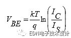
Formula 1)
among them:
k is a Boltzmann constant equal to 1.38×10⁻²³ J/K;
q is equal to 1.6021765×10⁻¹⁹C;
T is the temperature in K.
Equation (2) shows the VBE(N) value of the base-emitter of many parallel transistors.
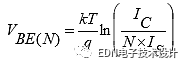
Formula (2)
If the current source IC is switched from one pin to the other, Equation (3) shows the difference between the two base-emitter voltages.

Formula (3)
Through calculation, it is concluded that:
CONSTANT=k × ln(N)/q or 86.25×10⁻⁶ × ln(N).
Conceptually, it lets you know how to measure temperature quickly at the IC level. A few improvements have been made to the circuit in Figure 1, with IC temperature sensing accuracy as high as ±0.4oC.
Output
Now that we have accurate temperature readings, it is important to present this final value to the outside world. There are two basic methods for displaying temperature data: analog voltage or digital values.
The analog voltage output is very easy to read. With the appropriate temperature sensing device, you can capture an analog signal, convert it to a digital representation or feed it back to a point in the circuit.
The digital output capability of the temperature sensor is more interesting, with many output types available, but mainly 1-wire, 2-wire or 3-wire outputs.
The 1-wire digital output provides pulse width modulated (PWM) pulse count signals or simple threshold/switch signals. Both of these signals are useful in fan control circuits. The 2-wire digital output provides an I2C or SMBus signal. The digital result is a by-product of the internal analog to digital converter. You can also see digital outputs that represent threshold temperatures and possible error conditions. The 3-wire digital output provides an SPI interface.
Wafer-level packaging of temperature sensor devices
Every product has a development process from rough to fine, and the temperature sensor series is constantly improving. This product line will next have a huge breakthrough in the size of the device package. The housing of the latest temperature sensor components is in a wafer level package (WLP).
In 1998, Sandia National Laboratories and Fujitsu developed WLP. The package has been wafer level fabricated prior to the dicing process and its assembly is done using standard surface mount technology (SMT).
This packaging technology brings an ultra-small package shape and low θ junction-environment values. The size of this generation of temperature sensors dwarfs the standard 0.1μF capacitor in a standard 0603 package (Figure 2).
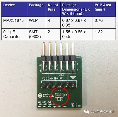
Figure 2: The WLP temperature sensor (U1/MAX31875) is smaller than the 0.1μF capacitor (C1) of the SMT.
At the dinner table
Because of the small size of the new package, you can place the temperature sensor on the PCB as you would for salt and pepper on the dinner. The latest generation of temperature sensors achieves an accuracy of ±0.4oC in a package that occupies only 0.76mm2 of PCB area. So what is the dish tomorrow?
The above is the How to use temperature sensor to easily solve -55 to 200oC temperature sensing problem we have listed for you. You can submit the following form to obtain more industry information we provide for you.
You can visit our website or contact us, and we will provide the latest consultation and solutions
Send Inquiry
Most Popular
lastest New
Send Inquiry